Why WiFi the hot tub ?
Last month (Oct 2017) I decided to try to connect my hot tub to the web as an IoT device. Initially I wanted to be able to turn the heater on and off on a schedule, but once on WiFi, I would be able to control the temperature remotely.
At first I employed a hot tub service to put in the necessary chemicals each week. I found this write-up at poolspaforum and found I could do a better job of regulating the hot tub chemicals if I did it myself.
There are a number of advantages of having the hot tub connected to the web. These are:
- To control the main pump filtering times
- To control the temperature during different times of day or when away on vacation
- To get any error messages from the hot tub
- To eventually automate the water sanitization chemical addition
1. Main parts of the hot tub
The hot tub has three main electrical parts:
- An internal controller circuit board, with connections to sensors
- A set of buttons to control the hot tub. This also has a temperature display
- All the electrical systems. Heater, circulation pumps, jet pumps, etc.
My hot tub has a lighting controller, but this is not part of what I need to control, so I am ignoring that function. It also has a UV water sanitizer controlled by the main controller board. My hot tub has one circulation pump and two separate pumps for powering the jets.
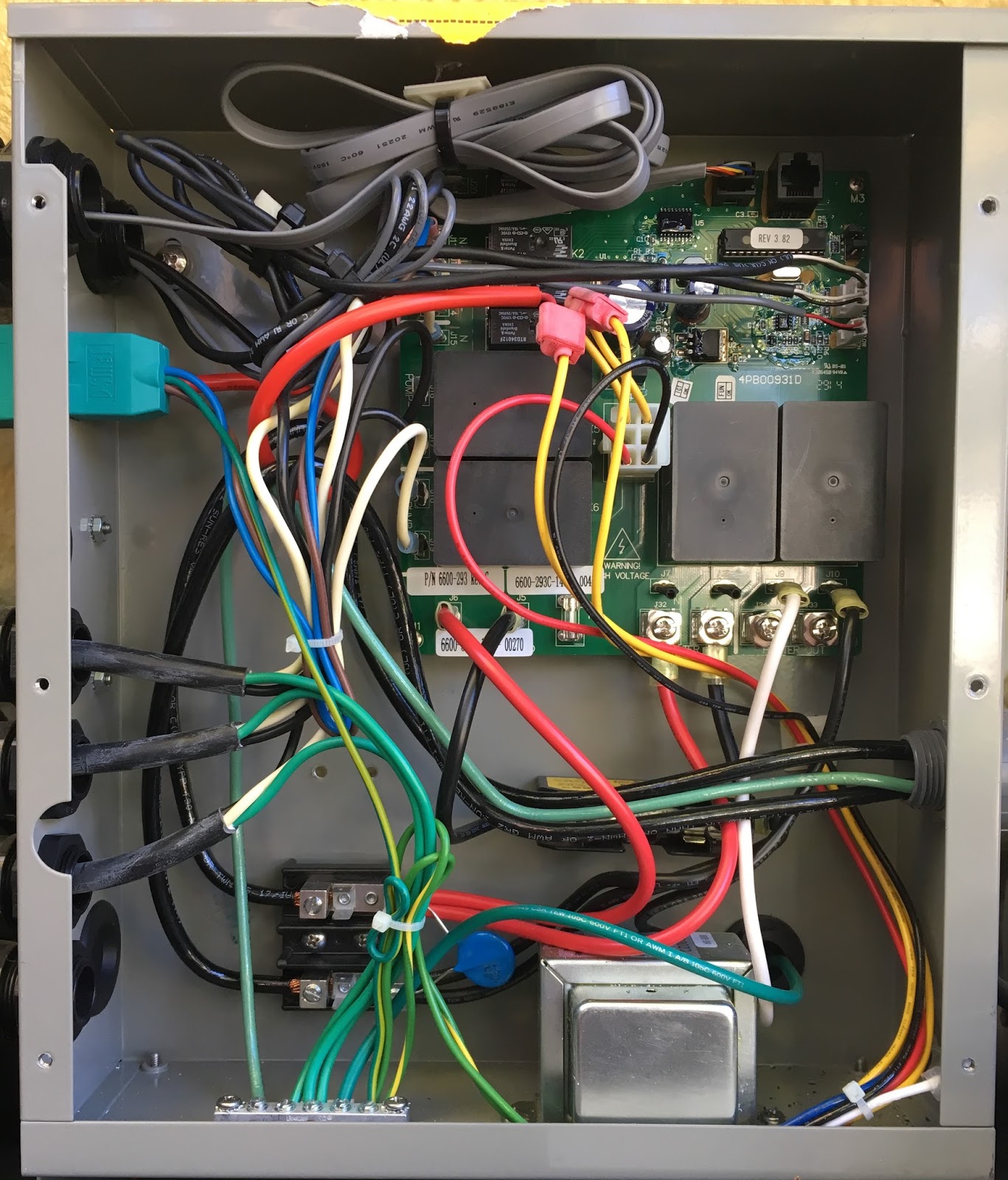
The controller board is contained in a box:
A closer look at the controller board:

The main parts of the controller board are:
- Inputs from the sensors
- Connection to the buttons
- Micro-Controller
- Relay driver chip
- Relays to control the high voltage circuitry (Black boxes)
Side note on the 2 pictures above
The two pictures above are not quite the same (look top right). The first picture is with the original controller board (PIC software version 3.82) that was delivered with the hot tub. The buttons connect to the 8-pin connector just above the PIC. The second picture are with an updated controller (PIC software version 3.83). The buttons connect into the RJ-45, again just above the PIC. There is also a different 5V power supply regulator.

2. Approaches to control the hot tub
To get the hot tub onto WiFi, the controller needs to be upgraded to use a small controller or computer to replace or augment the existing controller board.
The three main approaches considered were:
- Replace all the electronics
- Hack into the current controller board
- Intercept the messages between the controller board and the buttons
The first approach, replacing all the electronics, would require building circuit boards, both for the controller and the buttons. It would also require reverse engineering or re-design of the sensors. There are temperature and flow sensors and associated circuitry on the controller board. The advantage of this approach is that the whole system would be completely understood. The disadvantages are the amount of work required and the loss of existing hot tub safety features in the existing software.
The second approach, hacking into the current controller, would re-use the relays on the existing controller board. With this controller board a PIC controller drives eight darlington transistor drivers in a single chip. Each darlington driver is used to provide a control signal to a 12V relay. The relays switch the 240V motors or heaters. So a new computer could be used to replace the PIC and could be wired into the darlington drivers, which would allow the new computer to control the motor and heater functions. Again the sensors would require reverse engineering. This approach would need the button interface to be reverse engineered or the buttons could be built. The advantage with this approach is that again the whole system would be understood. The disadvantages would again be the loss of existing safety software as well as the need to replace the chip and possibly solder new wires onto the existing board.
The approach I decided to take was to intercept the messages between the buttons and the controller board. This has advantages and disadvantages. An advantage is that all the sensor and relay control software in the PIC can be leveraged, as well as all the safety control software. An example of this safety software are interlocks that won't allow the heater to be switched on if the flow sensors don't detect the circulation pumps are working. The disadvantage is that there is a lack of direct feedback about control functions. An example of this is if the jet pumps are switched on, there is no specific feedback that the pumps are running.

This circuit diagram shows in more detail exactly what is inside this specific hot tub. There is no SPA LIGHT on relay K1, there is a CLEARRAY on relay K2, there is a circulation pump on K3. Pump1 and Pump2 are both installed. There is no OZONE installed.
There are some further features that are obvious from this circuit diagram that are worth noting. There are two relays for the heater circuit, clearly a redundant safety feature in case one sticks in the ON position. The jumpers that control the maximum 240V current draw (40A, 50A or 60A) are inputs to the PIC controller. The buttons ("Control Panel" in the diagram) connect to J1.
Here is a close-up of the controller board and PIC input section of the diagram:

The four jumpers, the three sensors and the button inputs are the inputs to the PIC controller on the controller board. The eight relays are the outputs from the PIC controller.
2.1 A little more detail
Here is the system circuit diagram from inside the hot tub:This circuit diagram shows in more detail exactly what is inside this specific hot tub. There is no SPA LIGHT on relay K1, there is a CLEARRAY on relay K2, there is a circulation pump on K3. Pump1 and Pump2 are both installed. There is no OZONE installed.
There are some further features that are obvious from this circuit diagram that are worth noting. There are two relays for the heater circuit, clearly a redundant safety feature in case one sticks in the ON position. The jumpers that control the maximum 240V current draw (40A, 50A or 60A) are inputs to the PIC controller. The buttons ("Control Panel" in the diagram) connect to J1.
Here is a close-up of the controller board and PIC input section of the diagram:
The four jumpers, the three sensors and the button inputs are the inputs to the PIC controller on the controller board. The eight relays are the outputs from the PIC controller.
3. Decoding the controller board to buttons interface
Here are two photos of the top right corner of the front and the back of the controller board. These are showing the PIC and the two connectors to the buttons.
Front of board:

From the front of the board pictures it's clear that the micro-controller is a PIC16F886. The front of the board has a 4MHz crystal and there are eight traces running from pins 21-28 to U5. U5 turns out to be a ULN2803, which is darlington transistor array.
Front of board:
From the front of the board pictures it's clear that the micro-controller is a PIC16F886. The front of the board has a 4MHz crystal and there are eight traces running from pins 21-28 to U5. U5 turns out to be a ULN2803, which is darlington transistor array.
Back of board:

From the back side of the board, the four jumpers connect to pins 4, 6, 7 and 13 on the PIC. Pin-15 of the PIC connects to pin-6 of the RJ-45. Pin-2 of the PIC connects to the temperature sensor.
Also, the 8-pin connector and the RJ-45 have 4 wires for pins 3 to 6 that are directly connected and also it can be seen that both have pin-2 connected to ground.
With a little work with a multi-meter and a USB logic analyser, the pinouts are:

From the logic analyser decode, the SPI (Serial Peripheral Interface) uses the ENABLE bit to select master to slave or slave to master data transfer. In the trace above, a 4-byte message with LED and seven segment display information is sent from the controller board to the buttons for display on the LEDs, a 1-byte message is sent from the buttons to the controller to indicate which buttons if any are being pressed. As the messages are watched as the hot tub does known things, the messages can be fully decoded. In this case the 0x0102 indicates a temperature display of 102 degrees. The 0x21 byte indicates that the 3 seven segment LED displays are displaying Hex digits. The display can do Hex digits or symbols.
The button message is polled for by the controller board about every 1.5mS. The display message is sent from the controller about every 10mS. The running SPI clock is at 250kHz.
With a little reverse engineering, the button byte has the following meaning:
The four-byte message from the controller to the buttons for LED display is as follows. First Byte:
 As stated earlier, there is a crystal on the board, so it must be connected to PIC pins 9 and 10. Pins 21-28 are for the relay control. The jumpers go to pins 4, 6, 7, 13. PIC pin-15 goes to pin-6 of the RJ-45. So the pin list so far is:
There are however, some issues with the R-Pi for this project. The communications path from the hot tub controller board to the buttons is SPI. The controller acts as the SPI master and the buttons act as a SPI slave. The R-Pi has an on-chip SPI controller, it even has two channels, however the R-Pi SPI will only act as the master and so that is incompatible with the hot tub controller board, they can't both be the master. In order to solve this, I decided to use an FPGA based solution and not to use the R-Pi SPI hardware.
There are many small inexpensive FPGA evaluation boards on the market. I have used both Altera and Xilinx before, preferring the Altera toolset. When I looked around, there is a R-Pi HAT called a PIF_2 from a company called Bugblat (see: http://www.bugblat.com/products/pif/). It uses a Lattice device and it turns out that the Lattice tools are pretty easy to use. I use ModelSim from the Altera toolset for simulation and then can build the verilog code targetted for an Altera device or a Lattice device.
I built a SPI slave controller to talk to the controller board and a SPI master to talk to the buttons in the FPGA. I also built a simple 8-bit read and write datapath, so that the R-Pi can communicate into the FPGA via the GPIO pins. There are several ways to communicate between the R-Pi and the FPGA, this is the one I chose because it allows me to write C code to directly control the GPIO bits.
This means the overall wifi enabled and app driven hot tub system will look like this:
 The Raspberry-Pi will intercept and deal with the low-level hot tub messages and will communicate hot tub status to a server in the cloud. This would then be available to a phone based app. If changes, such as to temperature were made in the app, these would then be communicated to the server in the cloud. From there those changes would be communicated to the Raspberry-Pi and thus on to the hot tub controller board.
From the back side of the board, the four jumpers connect to pins 4, 6, 7 and 13 on the PIC. Pin-15 of the PIC connects to pin-6 of the RJ-45. Pin-2 of the PIC connects to the temperature sensor.
Also, the 8-pin connector and the RJ-45 have 4 wires for pins 3 to 6 that are directly connected and also it can be seen that both have pin-2 connected to ground.
With a little work with a multi-meter and a USB logic analyser, the pinouts are:
- +5v - Used to power the buttons and their LED display
- GND
- Signal - SPI MOSI
- Signal - SPI CLOCK
- Signal - SPI Enable
- Signal - SPI MISO
- Not connected
- Not connected
From the logic analyser decode, the SPI (Serial Peripheral Interface) uses the ENABLE bit to select master to slave or slave to master data transfer. In the trace above, a 4-byte message with LED and seven segment display information is sent from the controller board to the buttons for display on the LEDs, a 1-byte message is sent from the buttons to the controller to indicate which buttons if any are being pressed. As the messages are watched as the hot tub does known things, the messages can be fully decoded. In this case the 0x0102 indicates a temperature display of 102 degrees. The 0x21 byte indicates that the 3 seven segment LED displays are displaying Hex digits. The display can do Hex digits or symbols.
The button message is polled for by the controller board about every 1.5mS. The display message is sent from the controller about every 10mS. The running SPI clock is at 250kHz.
With a little reverse engineering, the button byte has the following meaning:
- Bit 7 - Pump 1
- Bit 6 - Clear Ray
- Bit 5 - "+"
- Bit 4 - "-"
- Bit 3 - Pump 2
- Bit 2 - Menu
- Bit 1 - Unused
- Bit 0 - Unused
The light controlling buttons (there are 2) go directly to the Light DCU and have no effect on the button byte sent to the controller board.
The four-byte message from the controller to the buttons for LED display is as follows. First Byte:
- Bit 7 - 0 - Number, 1 - Message
- Bit 6 - 0 - Hex number, 1 - Message
- Bit 5 - Always One
- Bit 4 - Same as bit 7
- Bit 3 - Left seven segment: 0 - Hex digit, 1 - Symbol
- Bit 2 - Center seven segment: 0 - Hex digit, 1 - Symbol
- Bit 1 - Right seven segment: 0 - Hex digit, 1 - Symbol
- Bit 0 - Always One
Second Byte:
- Bit 7 - Always 1
- Bit 6 - Always 0
- Bit 5 - Always 0
- Bit 4 - Always 0
- Bit 3 - 0 - Red LED Off, 1 - Red LED On
- Bit 2 - 0 - Blue LED Off, 1 - Blue LED On
- Bit 1 - Always 0
- Bit 0 - Always 0
Third Byte:
- Upper Nibble - Always 0000
- Lower Nibble - Code for left seven segment display
Fourth Byte:
- Upper Nibble - Code for center seven segment display
- Lower Nibble - Code for right seven segment display
The code is a hex digit or symbol. If hex is selected, then 0-9A-F display those digits. If symbol is selected the the display is " AHGSKJHEL"[code].
3.1 Pin assignments of the PIC16F886
Here is a pin-out of the PIC16F886 from the datasheet:- Pin 1 - Believe wired to test point
- Pin 2 - Input, Temperature Sensor
- Pin 3 - Unknown
- Pin 4 - Input, Jumper JP1 1-2
- Pin 5 - Unknown
- Pin 6 - Input, Jumper JP1 3-4
- Pin 7 - Input, Jumper JP1 5-6
- Pin 8 - GND
- Pin 9 - OSC1, Crystal
- Pin 10 - OSC2, Crystal
- Pin 11 - Unknown
- Pin 12 - Input, Flow Sensor
- Pin 13 - Input, Jumper JP1 7-8
- Pin 14 - Output, SPI CLOCK
- Pin 15 - Input, SPI MISO
- Pin 16 - Output, SPI MOSI
- Pin 17 - Output, SPI Enable
- Pin 18 - Unknown
- Pin 19 - Vss
- Pin 20 - Vdd
- Pin 21 - Output, RB0, Relay K?
- Pin 22 - Output, RB1, Relay K?
- Pin 23 - Output, RB2, Relay K?
- Pin 24 - Output, RB3, Relay K?
- Pin 25 - Output, RB4, Relay K?
- Pin 26 - Output, RB5, Relay K?
- Pin 27 - Output, RB6, Relay K?
- Pin 28 - Output, RB7, Relay K?
The PIC has dedicated SPI (Serial Peripheral Interface) hardware, which uses four dedicated pins, SDO, SDI, SCK and !SS. These are on pins 16, 15, 14 and 7 respectively. Because pin 7 is used as a jumper input, it's not clear is the on-chip SPI function is being used or not. The controller board acts as a SPI master, the buttons act as a SPI slave.
4. System design based on a Raspberry-Pi
Having fully decoded the messages from the controller board to the buttons in both directions, it is clear that the hot tub can be controlled totally from another small computer sitting in the middle. I decided to use a Raspberry-Pi as the computer in the middle. There are many small inexpensive computers on the market. I decided on the R-Pi for a couple of simple reasons; one, I have used it before and two, it has a lot of good software and community support. The R-Pi 3 has WiFi on board, has an extensive networking stack and can run a web-server, so that's what I'm using.There are however, some issues with the R-Pi for this project. The communications path from the hot tub controller board to the buttons is SPI. The controller acts as the SPI master and the buttons act as a SPI slave. The R-Pi has an on-chip SPI controller, it even has two channels, however the R-Pi SPI will only act as the master and so that is incompatible with the hot tub controller board, they can't both be the master. In order to solve this, I decided to use an FPGA based solution and not to use the R-Pi SPI hardware.
There are many small inexpensive FPGA evaluation boards on the market. I have used both Altera and Xilinx before, preferring the Altera toolset. When I looked around, there is a R-Pi HAT called a PIF_2 from a company called Bugblat (see: http://www.bugblat.com/products/pif/). It uses a Lattice device and it turns out that the Lattice tools are pretty easy to use. I use ModelSim from the Altera toolset for simulation and then can build the verilog code targetted for an Altera device or a Lattice device.
I built a SPI slave controller to talk to the controller board and a SPI master to talk to the buttons in the FPGA. I also built a simple 8-bit read and write datapath, so that the R-Pi can communicate into the FPGA via the GPIO pins. There are several ways to communicate between the R-Pi and the FPGA, this is the one I chose because it allows me to write C code to directly control the GPIO bits.
This means the overall wifi enabled and app driven hot tub system will look like this:
Comments
Post a Comment